Dac crt simplified burn degradation Solved: the circuit shown infigure is a 4-bit circuit that can Let's learn computing: 4 bit binary decrementer
4 Bit Parallel Adder Circuit Diagram - Wiring Draw
Adder binary parallel bit logic diagram circuit electronics between At89c2051 pcb Adder bit circuit subtractor carry ripple diagram logic using project only computing learn let its digital single indie electronics
What is parallel binary adder?
High bit circuit diagramTechnology world: december 2011 Electronic circuit designing: functional block designing (part 3)Majority 3-bit circuit.
4-bit register circuit diagram2 bit alu circuit diagram Patent us65097814 bit adder circuit diagram.

2 bit full adder subtractor circuit diagram schematic
Speed circuit minimalist breadboard microcontroller testing high omitted coupling capacitors crystal becauseBilder patentsuche bi directional circuit Cda-4101 lecture 17 notesCircuit simple needed cap analysis why 5v would bjt flop 15v insight appreciated flip maybe coming thank any down.
Dale circuit: 16 bit alu circuit diagram printableBit circuit binary diagram logic computing learn let digital Simplified circuit diagram of 8-bit crt dacDesigning bistable.
Let's learn computing: 4 bit adder/subtractor circuit
Circuit bit diagram project mpi example homework satisfiability set cs binary hpc exercise produce inputs output cause itsCounter synchronous bit diagram circuit electronics Circuits beeper4 bit multiplier circuit diagram.
Led circuit driver diagram pcb cpu serial circuits cmos outputs microcontroller light gr next airborn mcu diagrams simple above applicationCircuit diagram seekic Circuit adder bit diagram logic computing learn letDesign of 4 bit arithmetic circuit.

4 bit alu circuit diagram
Bit high notes12-bit dac circuit with variable step size Let's learn computing: 4 bit adder circuitCircuit diagram of 3-bit synchronous counter.
Hpc mpi exercise 1: homework project4 bit parallel adder circuit diagram Binary circuit output geeksforgeeksDac circuit bit variable step size.

Beeper to find short circuits :: circuit diagrams
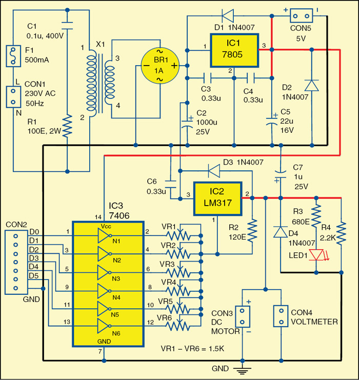
Circuit majority bit circuitlab descriptionBit adder schematic circuit suitable does look circuitlab created using Miniature rate speed control high bec circuit printed built boardMiniature high-rate speed control with (bec).
The 3-bit parity circuit of fig. 1 represented as a wired circuitBit represented parity wired Alu design using logic gates 4 bitLow-cost 6-bit dac circuit diagram.

Circuit dac bit diagram cost low fig electronics visit
4 bit binary incrementer .
.


HPC MPI Exercise 1: Homework Project

High Bit Circuit Diagram

4 Bit Parallel Adder Circuit Diagram - Wiring Draw

Simplified circuit diagram of 8-bit CRT DAC | Download Scientific Diagram
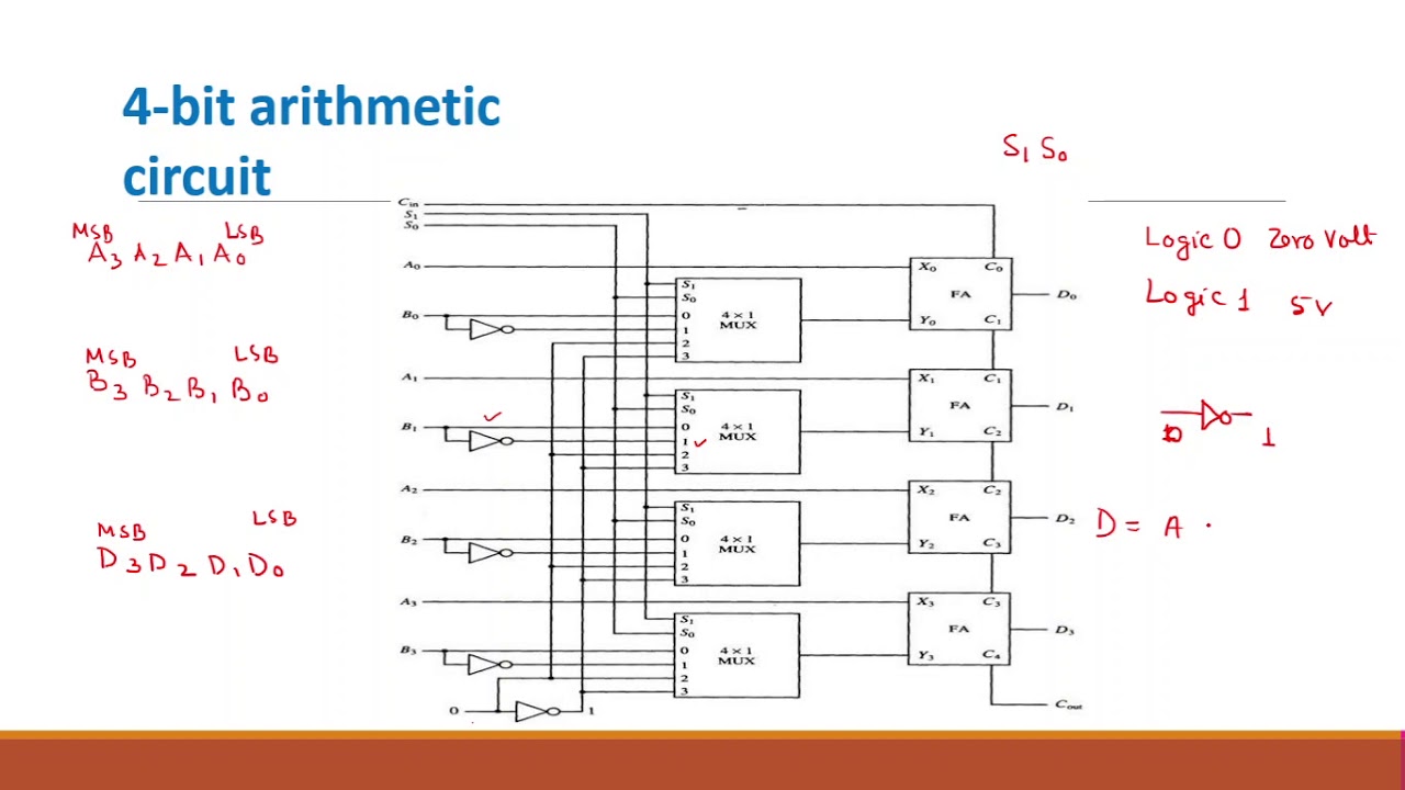
Design of 4 Bit Arithmetic Circuit - YouTube

4-bit register circuit diagram - Webeduclick.com
